WIRELESS
TRAILER LIGHT CONTROL
�����
�����������
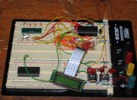 The picture at
left shows a bread board with the circuitry needed to run the LCD.� Each component of the project must be tested before
one can make a printed circuit board (PCB).��
All the transmission of data will be feed through the microcontroller
via a RF signal and then sent to the LCD screen to alert user about any
problems or simply to verify proper working order.
The picture at
left shows a bread board with the circuitry needed to run the LCD.� Each component of the project must be tested before
one can make a printed circuit board (PCB).��
All the transmission of data will be feed through the microcontroller
via a RF signal and then sent to the LCD screen to alert user about any
problems or simply to verify proper working order.
Figure
1.� Bread board with LCD components
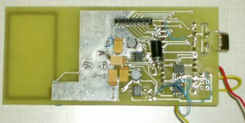
The PCB at left is used in the actual trailer light.� The antenna (large rectangle at left of
board) receives signal and then the microcontroller determines whether the
signal received is a turn, tail, or brake.�
LED�s on the other side of the board will become illuminated.� Very cool!
��������������� Figure 2. PCB of trailer
light circuit