Micromouse Team
Fall 2008
Micromouse Design 1.0
Team Members: Chris Gibson, Ambrose McJunkin, Tim Montague
Parts Involved:
� 2 DC Motors
� LCHB-SN754410 Dual H-Bridge Module
� M9S08QG8 Microcontroller
� Gyroscope
� 3 Ultrasonic Range Finders
� Aluminum Frame, Wheels
� Rotary Encoder
The motor will be driven by the Dual H-Bridge Module. The microcontroller will
communicate directly with the H-Bridge module to move the robot and change the direction
of rotation of the wheels, making it turn right or left. The gyroscope will be used to
keep the robot following a straight path. Also, the gyroscope will assist in helping the
robot make accurate and consistent 90� turns. The encoder will keep track of wheel
rotations, and from that data the microcontroller will calculate the distance the robot
has covered, lending to our algorithm. Two of the Ultrasonic Range Finders will detect
changes in maze geometry on the sides of the robot, alerting the robot to adjacent paths.
The last will be used to alert the robot to any immediate obstacles in front of it, such
as a dead end or L turn in the maze, and provide input to the algorithm in the
microcontroller that an alternate direction of travel must be sought.
Building it:
It�s necessary to get the robot built and performing simple movements before we can test
any algorithms. This means deciding on the robot�s hardware components will be the first
big step in our design process. We would like to get the robot moving as soon as
possible, so we are going to try to use the board, microcontroller, and chassis from the
EE101 robot. We believe this will speed up the building process and ordering overhead of
the project. We are going to replace the original DC servos with DC motors in order to
increase the robot�s speed. The motors we choose will fit well in the EE101 chassis with
room for the H-bridge and the digital gyroscope. The sensors will also be easy to mount
on the original frame. Any questions we have will get hammered out within the next week
and hopefully we will start putting it together by the next week.
The Algorithm:
The maze-solving algorithm is currently a work in progress. We made a simulator with
a virtual maze and robot to help develop the algorithm. The robot can be moved around
the maze and can simulate different sensors. With this tool, the algorithm can be
developed completely without a running robot. Then once the robot is built and running,
we can port the algorithm to the microcontroller with a minimum of difficulty. This will
help with our limited schedule. A number of different algorithms are currently being
discussed, including A* search. We intend to read some papers, implement different
algorithms and test them in our simulator until the best one is found.
The Encoders:
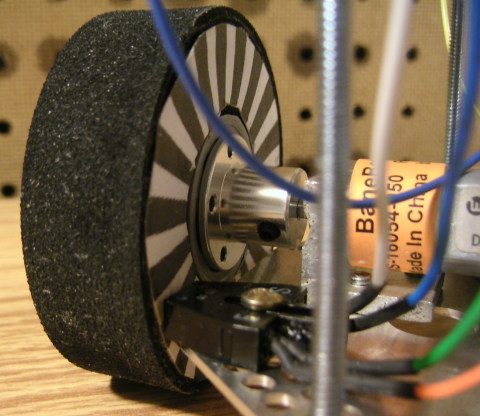
There is an encoder on each wheel of the robot which can be used to tell distance traveled.
Each wheel has a encoder wheel glued to it which consists of 38 white and black stripes.
Each stripe cooresponds to .5cm of movement, so when 36 stripes have been passed, the robot
has moved into the next square of the maze (each square is 18cm across). The stripes are
detected with a QRB1134 phototransistor.
Back to Main