Smart Power Strip
Colin Young, Travis Newell, Sam Sorensen, Joe Lutgen
Introduction
Background
Design Specifications
Circuit Layouts
Block Diagrams
Detailed Schedule
Project Costs List
Power Consumption
Future Directions
Parts List for Complete Build
Individual Responsibilities
Conclusions
As more and more of the world becomes concerned with conserving electric power and the fuels that generate electricity, there is a growing market for products to help the conscientious homeowner keep an eye on and minimize their power usage. Organizations such as Energy Star seek to minimize power consumption at the manufacturer level by providing buyer-recognizable certification on electronic devices. This certification is an easy way for consumers to discern energy-efficient products when shopping, providing an incentive to purchase Energy Star products over their less efficient cousins. This potential for increased revenue provides incentive to corporations to strive for energy-efficiency. Other organizations and products such as Google.org’s PowerMeter, Microsoft Hohm, and P3 International’s Kill-o-Watt aim to facilitate power-awareness by providing a framework for monitoring a home’s power consumption. PowerMeter and Hohm provide an intuitive user interface for recording and analyzing trends in power usage, while the Kill-o-Watt, a device that sits between the wall outlet and a piece of hardware, allows for measuring power consumption at the individual device level. The discontinuation of both PowerMeter and Hohm leaves an unfilled niche for an easy-to-use, centralized monitoring system. When integrated with monitoring hardware similar to the Kill-o-Watt, this monitoring system provides a convenient interface for measuring, controlling, and minimizing a home’s power consumption. The Smart Power Strip is designed to fit this niche and meet the needs of environmentally conscious consumers.This power strip will work like any other six-outlet, surge protected power strip, but will have the capability to wirelessly transmit statistics about power usage on each outlet. Additionally, the web-based user interface will help manage power use by controlling each outlet selectively.
Vampire electronics waste roughly 64 Megawatts of power and cost consumers nearly 4 billion dollars in wasted energy per year according to the US Department of Energy. This type of energy waste is what the Smart Power Strip will help to eliminate by giving consumers a means to monitor their power usage and actively shut down electronics completely when not in use. Also this device will have to be priced somewhere in the median between mid-range power strips, that senses when someone is gone from a room for more than ten minutes and shuts everything down on the power strip, and the high end of power control and monitoring, where a consumer can hire an electrician to install power monitoring and controlling equipment.
Vampire or standby power is loosely defined as the power used or wasted by electronics while not in active use. Some devices utilize vampire power in a useful manner to provide persistence features such as maintaining clock settings between active sessions, convenience features such as powering the necessary hardware to respond to remote controls, and to eliminate long initialization times by keeping the hardware in a semi-powered state, such as powering the tube heater in CRT displays. Other devices have no advantageous use of vampire power, such as a powered but disconnected mobile device charger or an uninterruptible power supply (UPS) with no active system connected.
The Californian Energy Commission estimated in 2008 that standby modes account for approximately 22% of a home’s power consumption. The US Department of Energy advises that by eliminating vampire power usage, average savings on utility bills lie in the area of $100 yearly, however this depends on local electricity rates. As most electricity is generated using fossil fuels such as oil or coal which produce carbon monoxide and other pollutants, minimizing vampire power will extend the lifetime of existing fuel supplies, reduce air pollution and acid rain, and potentially decrease the rate of global warming, of which increased levels of carbon monoxide has been implicated as a major contributor.
While the elimination of vampire power will not resolve the impending fuel and climate crises, it will grant mankind additional time to research and implement solutions to these potentially world-altering catastrophes.
Figure 1: Overview of entire smart power strip
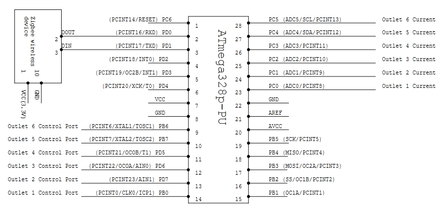
Figure 2: Detailed Schematic of power strip micro controller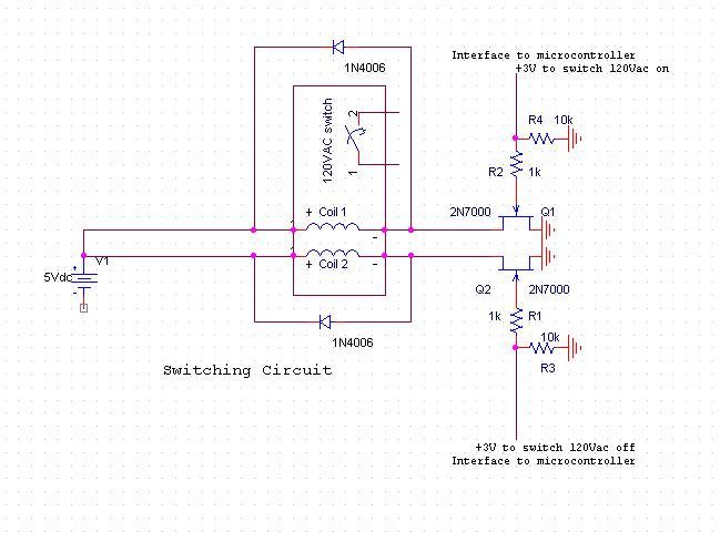
Figure 3: Detailed schematic of switching circuit
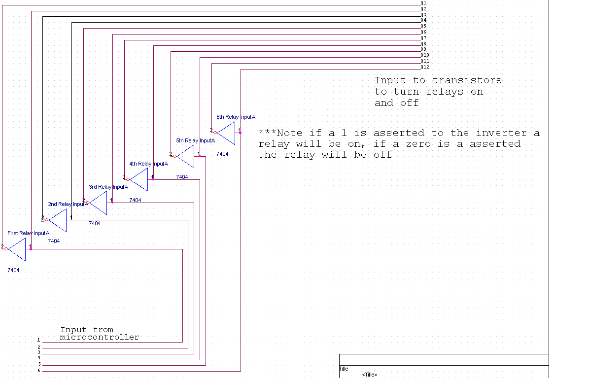
Figure 4: Detailed schematic of the connection between the Microcontroller and the relays involving the inverter going to the transistors
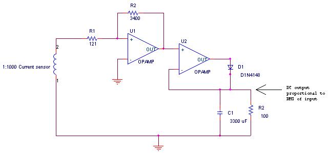
Figure 5: Detailed schematic of current sensor. The current sensor takes the line current and divides it by 1000 and then the Op amp amplifies it by 28 and then the peak is converted to a DC output. This signal feeds into the micro controller. The micro controller uses an equation to get RMS power Prms = 120*Vdc*0.707*1000*28. The 120 is the line voltage which is simply approximated because the electric utility is required to give 120 Vrms within 5% at the outlet.
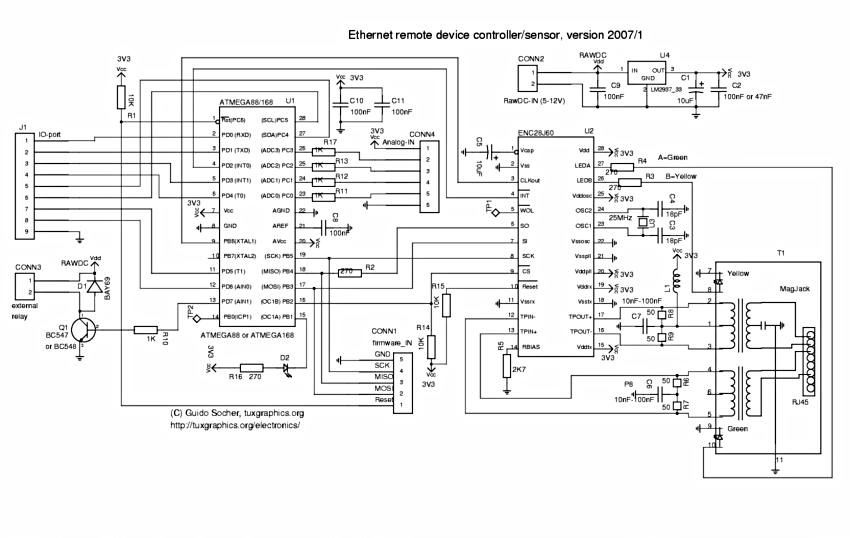
Figure 6: Detailed schematic of the AVR webserver/Ethernet controller
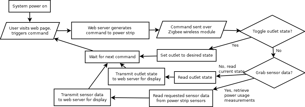
Figure 7: The figure above shows the flow of information passing from the user to the power strip.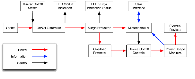
Figure 8: In this section the user requirements are looked at with more depth. Figure2 above shows a high level flow of the power information and control of the Smart Power Strip.
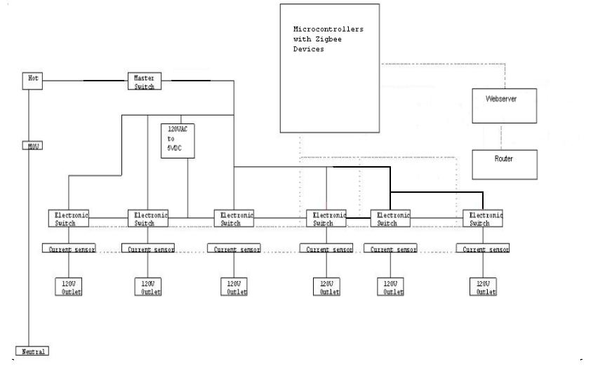
Figure 9: The above figure shows how the current sensors and electronic switching devices correlate with the micro-controllers.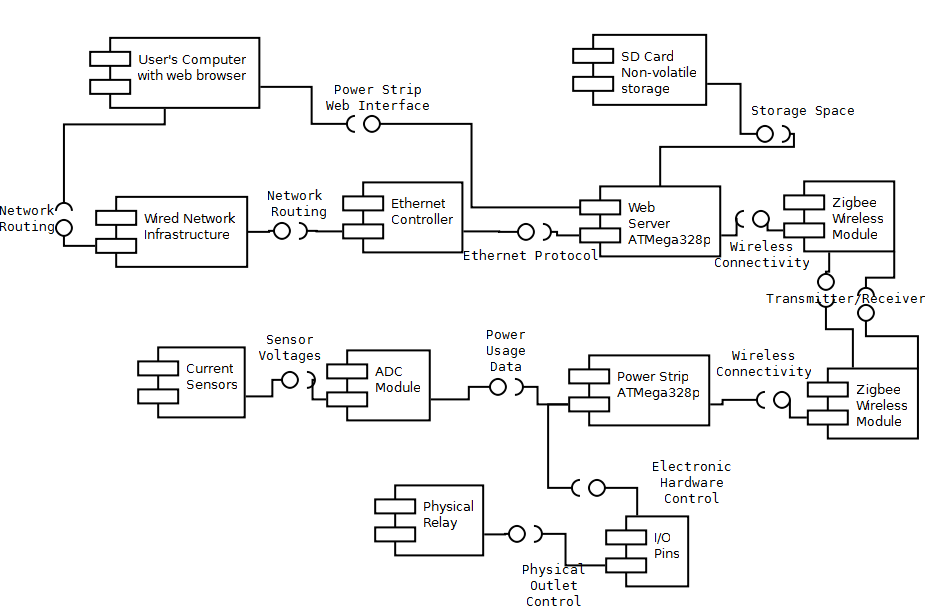
Figure 10: This UML component diagram models the interfaces provided and used by the various modules in the smart power strip.
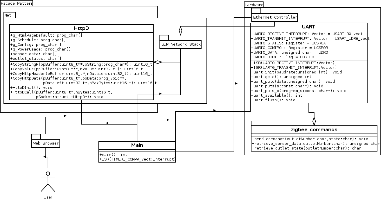
Figure 11: The above UML diagram describes the interactions of the various components on the web server.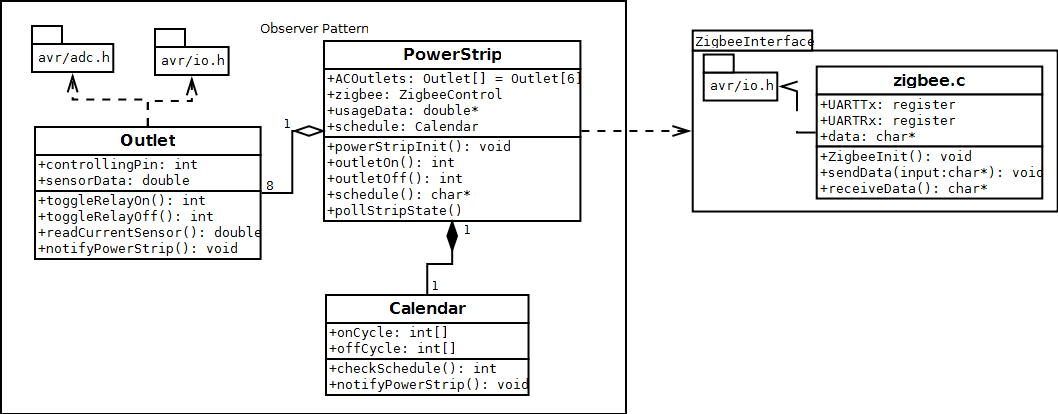
Figure 12: The above UML diagram describes a high level view of the interactions of the various components on the power strip.
Future Directions
This project has potential possibilities in the future. Calendars could be added to control on and off time of each outlet, optimization suggestions could be made to the user through an algorithm to save power, the current sensors could be upgraded to true RMS detectors to reduce power recording error, multiple Smart Power Strips could be linked together through one web browser. The electronics could be shrunk into a smaller case for a more compact look.
QTY | Part Description | Part number/location | PricexQuantity |
2 | Zigbee wireless antenna | sparkfun.com/8665 | 45.90 |
1 | AVR webserver | shop.tuxgraphics.org | 39.98 |
1 | Ethernet controller | ENC28J60 | 3.86 |
2 | ATmega 328p | 9.98 | |
6 | Latching Relays | Z2598-ND digikey | 47.58 |
1 | Doughnut current sensor(20kHz) 1:1000 | 553-15-46-ND digikey | 2.97 |
1 | Doughnut current sensor(60Hz) 1:1000 | TE2274-ND | 8.93 |
2 | Breakout Board for XBee module | BOB-08276 | 9.46 |
1 | 2GB SD card | Transend TS2GSDC newegg.com | 7.99 |
1 | Surface mount SD socket | 101-00405-75 digikey | 3.74 |
1 | 120VAC/12VDC wall wart | SK3386 skycraftsurplus | 5.00 |
1 | 14 AWG AC plug | CCM1819 digikey | 10.44 |
1 | 15 amp GFCI 120VAC wall outlet | GF15WLA grainger.com | 19.10 |
10 | 1N4006FSCT-ND Diodes | digikey | 2.23 |
10 | 2N7000FS-ND MOSFET transistors | digikey | 3.02 |
5 | SPDT Relay | Digikey Z2598-ND | 39.65 |
1 | 17”x6”x3” Aluminum Case | Digikey 377-1022-ND AC-433 | 32.80 |
1 | 6”x5”x4” Aluminum Case | Digikey L118-ND | 13.53 |
5 | Current Transformer | TE2274-ND | 44.65 |
3 | SPDT Relay | Digikey Z2598 | 23.78 |
2 | LM3940 | Brent’s stockroom | 4.00 |
2 | ATmega328 micro controller | Tux Graphics | 13.07 |
6 | Op amp quad | 497-2980-5-ND | 7.62 |
1 | True RMS detector | AD8436ACPZ-R7CT-ND | 11.36 |
1 | AVR webserver & enc28i60dip | Digikey | 48.60 |
1 | XBee 1mW Antenna & breakout board | Digikey | 29.54 |
1 | 2mm 10 pin XBee socket | Digikey | 5.64 |
Total | $494.42 |
Figure 13 Total project costs with $500.00 budget
The energy consumption of the Smart Power Strip comes in at about 13.14 kWh per year based on the constant 1.5 W in Figure 13. The average US home consumes 1100 kWh of vampire energy per year according to the U.S. Energy Information Administration. The power strip consumes less than 1% of the energy wasted in the average home. If the average person spends 8 hours a day sleeping and 8 hours at work, that is 16 hours when those outlets can be turned off. If every device contributing to the 1100 kWh vampire energy were regulated by the Smart Power Strip and was turned off when the homeowner isn’t using them, this would cut back on 66% of their wasted energy, a cost savings of $63.30 per year at a rate of 8.72 cents per kWh in Montana.
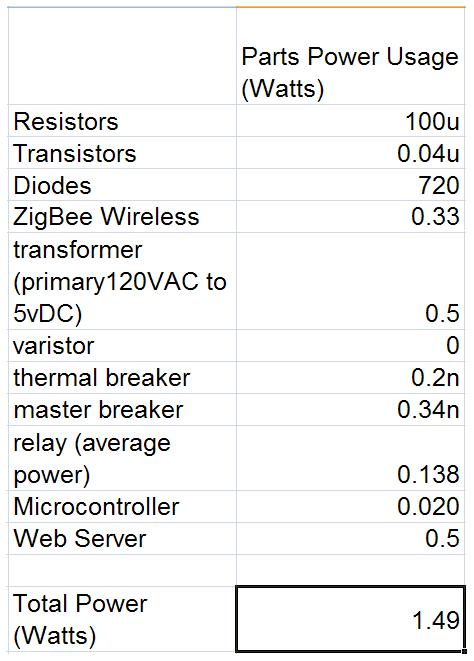
Figure 13 Power consumption of the Smart Power Strip.
Due to the incompleteness of the microcontroller on the power strip, the functionality of the system as a whole is rather limited. In our tests, we have shown that we can control outlets, the current sensor measurements are accurate, the web server can send and receive commands over the wireless module, and those commands can be triggered by a user from the web interface. The calendar scheduling and long-term data logging capabilities were deemed second-tier with respect to the core functionality listed above.
This project investigated and made a product that looked at and attempted to solve the issue of vampire electricity in modern day electronics. This project could be expanded in the future to accommodate multiple power strips in a home, as well as, incorporate USB power outlets. The webpage could add a calendar, and optimization recommendations for more efficient outlet usage.
Joe Lutgen was responsible for designing, assembling, and programming the microcontroller in the power strip. This microcontroller reads from Colin’s current sensors and the current state of the outlets, turns outlets on or off by command of the web server, and transmits power consumption data back to the web server for storage or display.
Sam Sorensen worked on the Smart Power Strip’s web server, enabling it to display different web pages and trigger different commands based on incoming HTTP data. The web server is also capable of transmitting and receiving data through the UART connection to the Zigbee wireless module. The sent data consists of commands to the power strip, and the received data is sensor measurements from the power strip, which is then displayed in the appropriate web page.
Travis Newell’s responsibilities include everything pertaining to the physical switching of the outlets on and off. This includes building 6 identical switching circuits for each outlet and will include powering all of the transistors and relays included in each circuit. Each one of these circuits will have to be able to take a voltage stimulation from Joe’s microcontroller in order to turn on each relay, and thus each outlet. Travis will also be working alongside Colin in case design to build a suitable housing for the smart power strip that addresses safety and ease of troubleshooting.
Colin Young built the current sensors that took line current values, and he converted them to a DC voltage that the microcontroller could interpret. Colin built the power system to supply power to all of the electronics in the Smart Power Strip case. He also worked on controlling the $500.00 budget, building the case, designing the electronics layout in the case, and mounting the outlets and incoming 120 VAC power line.
The Smart Power Strip could be developed into a mainstream product if further work was done to reduce the size and cost of the unit. This project served the students working on it by teaching them design skills, implementation skills, and team building. Some of the lessons learned by the team are that communication is key, staying on schedule is a Herculean task, and always overestimate how long each section will take to complete. It is better to come out ahead of schedule than to get behind schedule.
"Energy Use of Household Electronics: Taming the Wild Growth." California Energy Commission. California State Government, Sept. 2008. Web. 15 Nov. 2011. <http://www.energy.ca.gov/2008publications/CEC-500-2008-064/CEC-500-2008-064-FS.PDF>.
Raphael, Jr. "Unplug for Dollars: Stop 'Vampire Power' Waste | PCWorld." PCWorld - Reviews and News on Tech Products, Software and Downloads | PCWorld. PCWorld, 09 Nov. 2008. Web. 15 Nov. 2011. <http://www.pcworld.com/article/153245/unplug_for_dollars_stop_vampire_power_waste.html>.
Schueler, John. "Are Energy Vampires Sucking You Dry? | Department of Energy." Energy.gov | Department of Energy. U.S. Department of Energy, 31 Oct. 2011. Web. 15 Nov. 2011. <http://energy.gov/articles/are-energy-vampires-sucking-you-dry>.