Before the planning and development phase of the design process was completed, the layout of the spectrograph needed to be developed. A description of the process and design of the spectrograph is developed below.
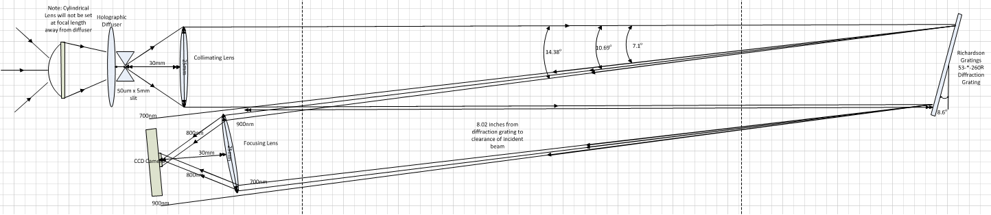
A collimating lens was placed the focal length, 30 mm away from the slit. The focusing lens was placed about 8 inches from the face of the grating with the sensor placed at the focus, 30 mm. The lens is placed 8 inches from the diffraction grating face because it will take around 8 inches for the diffracted rays to clear the incident collimated beam. This also sets the distance between the collimating lens and diffraction grating to be at least 8 inches. The focusing lens will be angled at 9o such that all of the 800 nm rays are captured at a normal to the focusing lens. This will result in the 800 nm wavelength of light to be focused in the middle of the CMOS sensor. It is inherent that not all of the light reflected off of the grating will be captured by the focusing lens as the spot size incident on the grating is equal in diameter to the focusing lens. The beam then proceeds to elongate in the dimension of spectral spreading this causes vignetting of the slit imaged spectrum when a fraction of the beam is captured by the focusing lens. This results in the extreme wavelengths at 700 nm and 900 nm to have a lower relative power on the sensor face compared to the 800 nm wavelength which should be entirely captured on the sensor. When the system is being prototyped an effort to maximize power captured by the focusing lens will be made by adjusting the incident angle of the diffraction grating such that the focusing lens can be moved closer to the grating, decreasing the effects of vignetting. A diagram of the Lens optical design layout can be seen below.
The system housing will be assembled using a metal frame in order to ensure stability and a planar system. Aluminum sheets will be cut to the desired dimensions. The box must be designed to be optically insulated. If any external light enters the system except through the optical slit, any optical power measurements will be compromised. To accomplish this optical insulation, the inside of the box will be painted with a low-reflection black paint in order to absorb as much undesirable light and reflected light as possible. The top and bottom box edges will be will be sealed with foam strips in order to create a system that is insulated optically and from moisture and weather. The optical components will be mounted on an aluminum mounting plate. A polymer window will be used to allow light to enter the system, while maintaining environmental and optical insulation. The optics will be mounted on this aluminum plate using lens mounts, posts and post holders from Thor Labs. The slit and diffraction grating will be mounted on the edge of the box, as opposed to mounted internally as shown in the figure. This will help minimize any additional light entering the box. Currently, the slit aperture is specified to be 5.32mm tall and 50um wide. This size will accommodate the height and power specifications of the camera. The slit may be widened to increase power while sacrificing resolution, or narrowed for the opposite effect.