
Key Accomplishments
ELE 101 Stock Car

EELE 101 Car
Building and testing the stock EELE 101 car gave valuable insight on where problems were with this car. Since the goal of our project was to build fast car, the stock EELE 101 would not work being anywhere close to the original. This car uses two servo motors to run the car, and turns using differential steering. Timing this car, it goes 3 meters in approximately 4.66 seconds at maximum speed. At this maximum speed, it would complete the full course in about 1 minute and 32 seconds. This is the milestone that we have to beat for our competition, thought our goal is to not just beat this by a little bit, but by a margin as wide as possible.
The EELE 101 car is shown to the right. It is a square design, with two thin wheels controlled by the server motors. There is a ball bearing wheel and 4 IR sensors on the fron to keep the car steady and on the line.
Delay of the Motor
With our car we have calculated the amount of time it should take our car to turn at full speed. We made these calculations off this graph in MatLab and we used the specs of the motor. It the car is running at full power it should be moving at around 1 meter per second. That is 600 rpm for the motor. Using that and the circumference of the tire and chassis we calculated how long it takes the car to turn differ amounts of degrees. 600 rpm is 10 rev per second. Dividing the circumference of the chassis by the circumference of the tire I found how many revolutions the wheel needs to turn in 360 degrees. Using this ratio we found the rate of turning in Hz by degree.
| Degree Turn | Time in Hz |
| 15 | .141 |
| 30 | .284 |
| 45 | .453 |
| 60 | .567 |
| 75 | .709 |
| 90 | .851 |
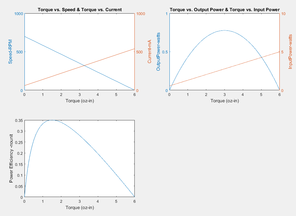
Torque vs Speed and Power Graphs
QTR (IR Sensors) and Microcontroller Delay
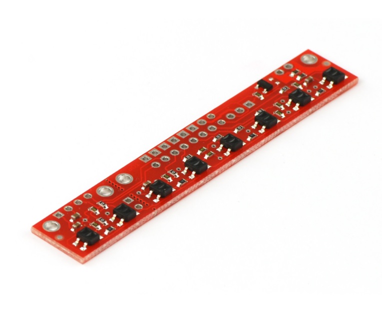
The QTR-8RC Sensor by Pololu.
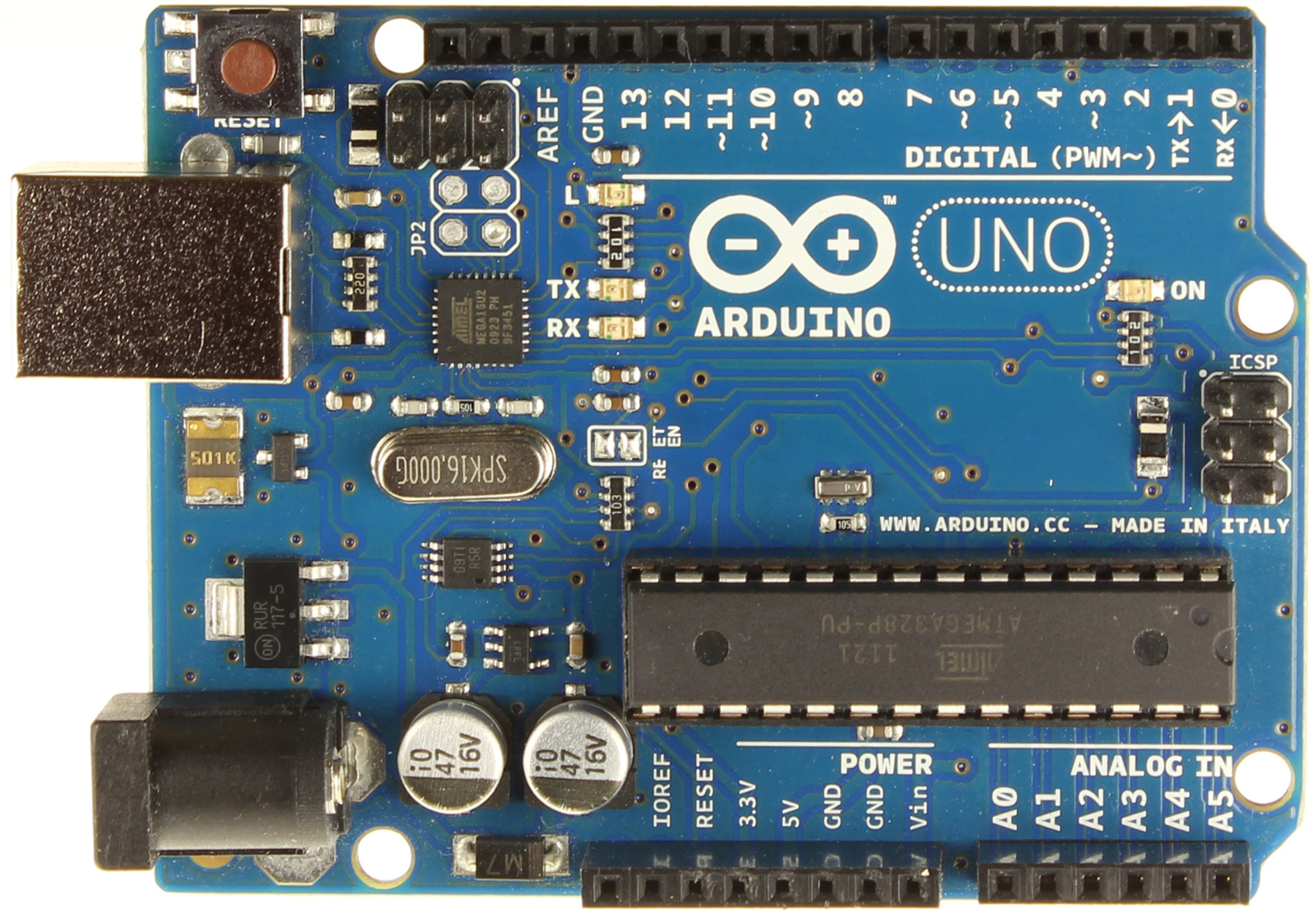
The Arduino Uno Microcontroller.
With the new QTR sensors, the QTR-8RC, we will be able to achieve accurate measurements faster than the original stock car. To achieve this we must meet two parameters. The first is the height of the QTR sensors. From their data sheet, the QTR sensors behave optimally at approximately 3 millimeters off of the ground. The second parameter is the amount of sampling rate that our microcontroller can support. The sensors require up to 1 kHz of sampling of all 8 sensors.
QTR-RC Sensor

The sensor we have chosen is the Pololu QTR-1RC reflectance sensor. It carries a single infrared LED and phototransistor pair. In order to make us of the sensor, we must first charge the output node by applying a voltage to the OUT pin. We are then able to read the reflectance by extrapolating the externally supplied voltage and timing how long it takes the output voltage to decay due to the integrated phototransistor. This measurement approach has several advantages, especially when multiple units are used since we will be using 5:
-
No analog-to-digital converter is required
-
Improved sensitivity over the output
-
Parallel reading of multiple sensors is capable with our microcontroller
The LED current-limiting resistor is set to deliver approximately 17 mA to the LED when VIN is 5V. The current requirement will be met by our microcontroller I/O lines, this allows the device to be powered up and down through an I/O line in order to maintain minimal power draw.
Micro Metal Gearmotor Bracket Pair
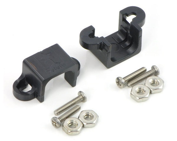
This compact bracket will allow us to mount our Sanyo-style micro-metal gearmotors. The black plastic bracket encloses gears and each bracket comes with two number 2 screws and nuts.
ATmega328P
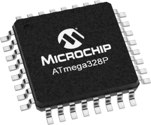
The Microchip picoPower 8-bit AVR RISC-based microcontroller(ATmega329P) features 32KB ISP flash memory with read-while-write capabilities, 1024B EEPROM, 2KB SRAM, 23 general purpose I/O lines, 32 general purpose working registers, three flexible timer/counters with compare modes, internal and external interrupts, serial programmable USART, a byte-oriented 2-wire serial interface, SPI serial port, a 6-channel 10-bit A/D converter (8-channels in TQFP and QFN/MLF packages), programmable watchdog timer with internal oscillator, and five software selectable power saving modes. We will be running the devices at 3.3V between the edge power conditions of 1.8-5.5 volts. The device runs at approximately 1 MIPS per MHz.
This was a good choice for the robot, as it has enough processing power, as well as being small and light for the small robot that it will control. This microcontroller has enough I/O pins to control the robot, as well as a fast enough clock to retrieve all the sensor measurements, make the needed calculations, and control the motors. This is all that is needed to move the robot around the track as fast as possible, and this microcontroller meets all the requirements, and is also very cheap compared to many of the other bigger options.
PCB Chassis

Our car will be built on a round PCB board with holes spaced on a 0.100" grid, two extended 2×7 male headers, two extended 1×2 maleheaders, one 2x7female header, two 1x2 female headers, four 7/8" nylon spacers, four 1-1/4" screws, and four nuts.
USB AVR Programmer
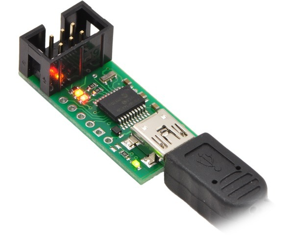
This device is a programmer for AVR-based controller. It includes a USB cable and an ISP cable. It emulates an STK500 on a virtual serial port, making it compatible with standard AVR programming software. There are two main help features that we will be using to debug our car during the subsystems development: a TTL-level serial port for general-purpose communication and a SLO-scope for monitoring signals and voltage levels.
The Pololu USB AVR Programmer is an extremely compact, low-cost in-system programmer (ISP) for Atmel’s AVR microcontrollers. It is designed to interface with our microcontroller. The USB AVR programmer connects to your computer’s USB port via an included USB A to mini-B cable and communicates with the programming software we decided to develop in. It accomplishes this through a virtual COM port using the AVRISP V2/STK500 protocol. The programmer connects to our robot car via an included 6-pin ISP programming cable.
This will not be a part of the robot, but as it is required to program the ATmega328P, so it is included in the parts list and the budget. The programmer connects to the robot, and is able to program the chip attached to the chassis of the robot.
Pololu Wheel 32x7mm Pair
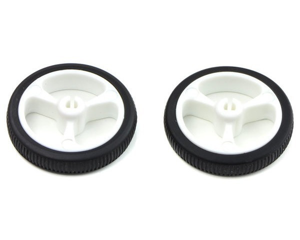
These white plastic wheels have silicone tires measuring 32 mm in diameter and press-fit onto the 3mm D output shafts that match the micro metal gearmotors. Using a prototype board with these wheels we checked that they had a coefficient of friction of over .5. What we measured was (5/9)=0.555 and that is better traction than our minimum measurements we made. The other reason these wheels were chosen is that they fit our proposed chassis and give us the correct ride height we need for our sensors.
Ball Caster with 1/2″ Plastic Ball

This ball caster will be mounted through a hole in the PCB chassis that uses the micro metal gearmotors and fits with our 32×7mm wheels chosen above. This ball caster is just the right height to keep the chassis level.The hole for this ball caster in the chassis has a diameter of 15.24 mm and has a side that is flattened by 0.762 mm.
Duel Motor Driver
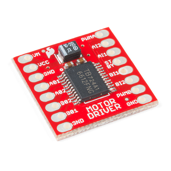
The TB6612FNG Motor Driver can control up to two DC motors at a constant current of 1.2A (or up to 3.2A for a short, single pulse). Two input signals (IN1 and IN2) can be used to control the motor in one of four function modes: CW, CCW, short-brake and stop. The two motor outputs (A and B) can be separately controlled, and the speed of each motor is controlled via a PWM input signal with a frequency up to 100 kHz. The STBY pin will be pulled high to take the motor out of standby mode. Logic supply voltage (VCC) can be in the range of 2.7–5.5VDC, while the motor supply (VM) is limited to a maximum voltage of 15VDC.
The stall current for each motor in our setup is 1079.166mA. This driver can supply 1.2A per motor so that meets our requirement with a little wiggle room. However we will still be far below the short pulse burst current limit. Finally, decoupling capacitors are included on both supply lines. All pins of the TB6612FNG are broken out to two 0.1" pitch headers; the pins are arranged such that input pins are on one side and output pins are on the other.
30:1 Micro Metal Gearmotor MP 6V

This gearmotor is a miniature medium-power, 6 V brushed DC motor with a 29.86:1(30:1) metal gearbox. It has a cross section of 10 × 12 mm, and the D-shaped gearbox output shaft is 9 mm long and 3 mm in diameter. These motors can be run at a slightly higher voltage and at 9.25V they have these characteristics:
Free run Rpm: 1125.41rpm
Free run current: 61.666 mA
Stall current: 1079.166 mA
Stall Torque: 12.333 oz-in
For the coefficient of friction for our tires (5/9) our max cornering speed is:
Vturn= ⎷(5*9)(g)(2ft)= 1.8224 m/s
Rpmmax is (Vturn/Cwheel)*(60sec)=1087.67 rpm
(Stall Torque x2)/wheel radius = Fapp= 36.8159 ozf = 10.235N
Fres = u*N = u*m*g = .481N
The actual rpm of the motor is:
1125.41rpm-((1125.4*0.481)/10.235)=1072.51 rpm which is 1.797 m/s = Vmax
For this reason as well as weight and size these motors were chosen because they are powerful enough to move the car right up to its cornering speed limit. That is important because we plan to have our car traverse the track at full speed even in the turns.
Fnet is our forward traveling force. Fnet= Fapp - Fres = 9.753N
a=Fnet/mass= 9.753/88.45 gr = 110.266 m/s^2
Time to top speed tts = Vmax /a = 16.296 milliseconds
Distance to top speed= d= (Vmax)(tts)+(.5)(a)(tts)^2 = 43.928mm
Race time is ((length of track)-(d))/Vmax + tts = 8.472 sec
Adjustable Boost Regulator 2.5 to 9.5V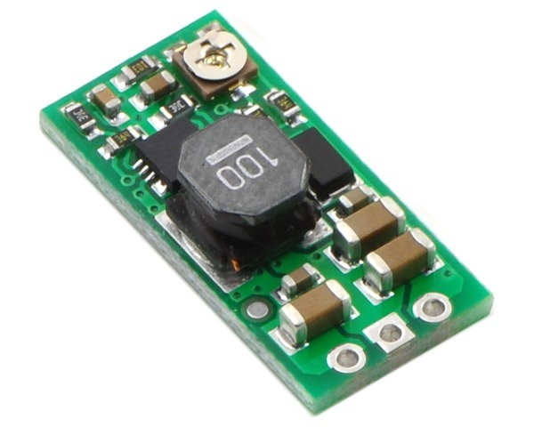
We will be using the Pololu adjustable boost regulator 2.5 to 9.5V as the main voltage controlling device. Due to us using a 7.4V battery source, we will be able to maintain a steady voltage of 9.25V with a trimmer potentiometer. It is contained in a 0.42″ x 0.88″ x 0.23″ package. Something to keep in mind is the product advises to keep the output voltage higher than the input voltages.
E-Flite 280 mAh 2S 7.4V 30C Li-Po Battery

This battery was chosen because it is small, lightweight, inexpensive, rechargeable, and LiPo batteries have the best energy density available right now. Our max current draw is 2.232 amps and we would like a minimum operating time of 60 sec per battery. With that in mind we need a minimum of 37.205mAh. This is over 7 times that and is 7 dollars.
Specs:
-
type: LiPo
-
Capacity: 280mAh
-
Voltage: 7.4V
-
Number of Cells: 2
-
Weight: 0.6 oz (16.9g)
-
Length: 1.5 in (39mm)
-
Width: 0.8 in (20mm)
-
Height: 0.5 in (13mm)
-
Application: UMX 2S Airplanes
-
Maximum Continuous Discharge : 30C (.280*30=8A)
-
Price: 6.99
7.4V-6.5V Voltage Regulator

This Voltage regulator was chosen because it steps the LiPo battery voltage from 7.4V down to 6.5V while still allowing the max current draw of 2.232 A we might need. It also has handy lights that tell us when the battery is low.
Specs:
-
Li-Po Battery Voltage (7.4V) regulated at 6.5V for receiver to work safely.
-
Maximum Input: 16V
-
Output: 6.5V / 3A
-
LED to indicate the voltage condition.
-
(Green LED - The voltage regulator is working properly)
-
(Red LED - Low voltage in battery, require recharge)
-
Lightweight, only 8g.
-
46cm wire Length for easy installation on different type of R/C.
Mini Pushbutton Switch: PCB-Mount, 2-Pin, SPST, 50mA
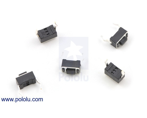
These small, two-pin, momentary tactile buttons are intended for mounting to PCBs, but they can also be plugged into standard 0.1" breadboards. They work well as reset buttons and can be connected to microcontroller inputs to serve as a user-interface components. They are intended for mounting to PCBs. It is noted in the product description that this button should not be used with voltages above 12V, and it should not be used to switch currents greater than 50 mA.
Specs
-
Activation force: 6 oz
-
Maximum rating: DC 12 V / 50 mA
-
On resistance: ≤ 50 mΩ
-
Off resistance: > 100 MΩ
-
Life: > 100,000 cycles