

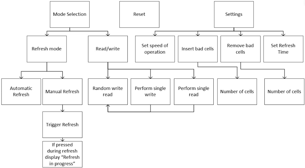
The screen will display basic menus, which can be navigated using the directional control pad, the select button, and back button. From these menus the user will be able to select different options for device operation such as the refresh rate time and whether defects are present.
The program will default to a sequence of reads and writes on random bit values, but users will be able to select other modes including: store to 1 specific cell; read from 1 specific cell; perform single refresh routine; and random read/write with refresh routine disabled.
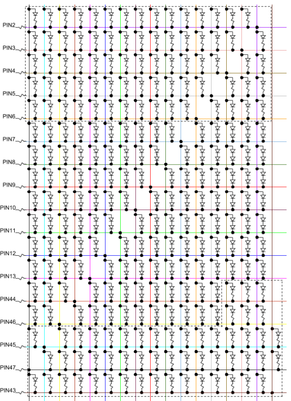
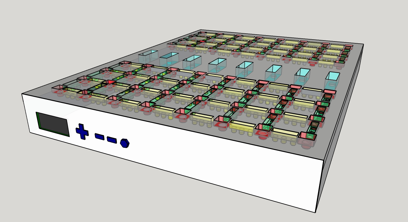
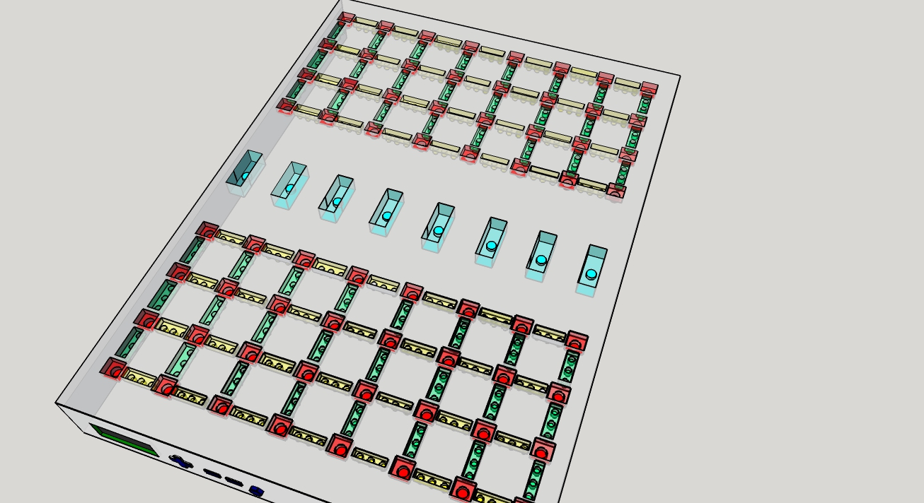
The LED’s will be wired in a charlieplex matrix to PWM digital I/O pins on the arduino. Of these LEDs, 72 will be wired to be turned on independently. These 72 LED’s will be used to represent the cells and sense amps of the DRAM in the device itself. There also exists 16 bitlines, with 9 LEDs per bitline, and 8 wordlines with 21 LED’s per wordline. Each bitline and wordline will have all the LEDs in the line illuminate at once, but because the forward voltage of the LED’s selected is 2.1 V and the supply voltage of the digital I/O pins is 5 V no more than 2 LED’s may be wired in series on a single output pin/input pin combination. For the LED’s in the bitlines and wordlines, 2 LEDs per output were wired which left a remainder of 16 individual LEDs at the end of each bitline and 8 LEDs at the end of each wordline left over. These remaining LEDs were wired in the same fashion as those of the cells and wordlines.
Between each pin on the arduino and the LED array is placed a resistor R1. These resistors are selected to limit the current through the LEDs that are placed in series with each other in the bitlines and wordlines. For the LEDs that are not in series with another LED, a resistor R is placed in series with the LED to help fine tune the current through those resistors. The resistors were selected to ensure the current through the device is what is needed for the forward voltage.
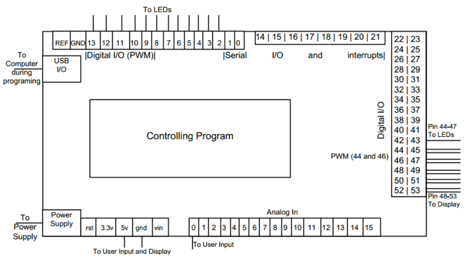
The Arduino Mega will use digital I/O pins 2 through 13 to drive the LEDs on the face of the board. Each of these pins will run in either high impedance mode, input mode, or PWM output mode depending upon the LED being lit. The duty cycle the pwm output each pin drives will depend upon the desired brightness of each LED. Because there are more output LEDs to drive than 14 bit charlieplexing can achieve, some digital pins will be needed to be configured for PWM manually using timed bit switching.
Digital pins 48 - 53 will be configured as digital outputs and used to drive the LCD output display. The 5 V supply and ground pin will also be used in the operation of the LCD output display.
Analog input 0 will be used in concert with the 5 V supply and the ground pin to both provide power to the input buttons and read the output of which button is pressed.
The device will be powered by a 9 V battery via a battery to 5.5x2.1 mm center-positive barrel jack adaptor.
The device will interface with the computer via a USB cable attached to its USB I/O port.
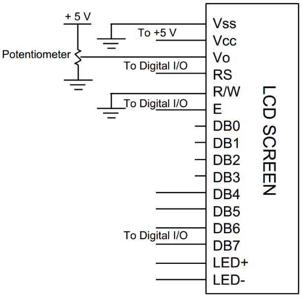
The LCD screen will receive power from the + 5V pin of the arduino via its Vcc pin, and will be grounded via a connection between the arduinos ground and its Vss pin. It will be tied to a read mode via a grounding of its R/W pin. The enable pin (E) and the register select (RS) pin that control the LCD’s memory storage will be attached to digital pins of the arduino. The brightness of the display control (LED+ and LED-) will also be attached to the arduino output pins. The contrast control of the LCD (Vo) will be wired to a potentiometer that receives its power from the arduino 5 V pin. Of the data pins that control the values written to/read from the registers of the LCD screen (DB0-DB7), DB5-DB7 will be connected to digital I/O pins and DB0-DB3 will be unconnected.
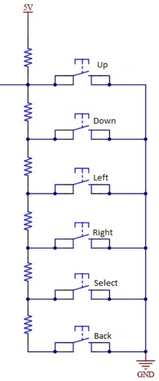
The button inputs of the device are driven by the 5 V pin of the arduino. When no button is pushed, the circuit is open and the arduino reads 5 V from its analog input. When the first button is pushed, the entirety of the 5 V is dropped across the top resistor and 0 V is read. When the second button is pushed the 5V voltage drop is divided between the first and second button and an intermediate voltage is read. The lower buttons also cause a voltage division, but with more resistance before the read voltage such that the lower the button is pressed the closer it gets to 5V. Note that if 2 or more buttons are pressed simultaneously only the top button will be registered as being pressed by the arduino, so only a single button at a time should be pressed.