Project Planning and Development
Functional Specifications:
The functional purpose of this product is to provide a visual
representation of what occurs in DRAM memory using LEDs. The user
must be able to write to and read from the memory in a way that can be
displayed by a 2 dimensional array of LEDs. There must also exist
a visual demonstration of charge leakage and a refresh routine to fix
the problem. Finally, there must be a mode that demonstrates
memory defects and presents a failure analysis solution to circumvent
the defects. The user must be able to select and execute
different modes from a user interface, which they can use with the aid
of an operation manual.
Design Metrics:
The first metric to measure the success of our system is how much the
system ends up costing to make. If we exceed the allocated budget
during the course of fabrication there will be insufficient funds to
make the required amount of units. The amount of units produced
is the second metric of success, to have this project be a success we
must deliver the requested amount of product. The next design
metrics are those of size and weight. In order for the product to
be easily portable, it must not be too large in either dimensions or
mass. The next design metric is the amount of power consumed by
the device. If they use too much power the device will quickly
run down its battery and need a replacement. Related to the power
consumed is the metric of heat produced. If too much heat is
produced, physical damage to the electronics can occur. The final
metric is durability. The more durable the system is the longer
it should last and the more successful a product it will be.
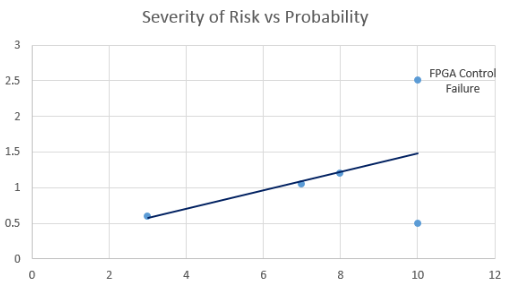
Risk Analysis1 .LEDs
If the LEDs overheat, do not respond to the FPGA, or emit wrong signal,
certain memory cells will not be available leading to an
inaccurate model of DRAM if not addressed.
2. Microntroller ControlIf the microcontroller controls fail, the LED array will not work and the system will be completely inoperable.
3. PC GUI
If
the PC GUI is not implemented, or is implemented incorrectly, the LED
array will not be operable from the computer and a major set of
requirements will not have been met
4. Manual InterfaceIf
the manual control system fails, the system must be run from the
computer interface and a set of requirements will not have been met.
5. Power SupplyIf
the power supply to the system fails, or is not sufficient to meet the
needs of the project, the system will not be able to operate at all.
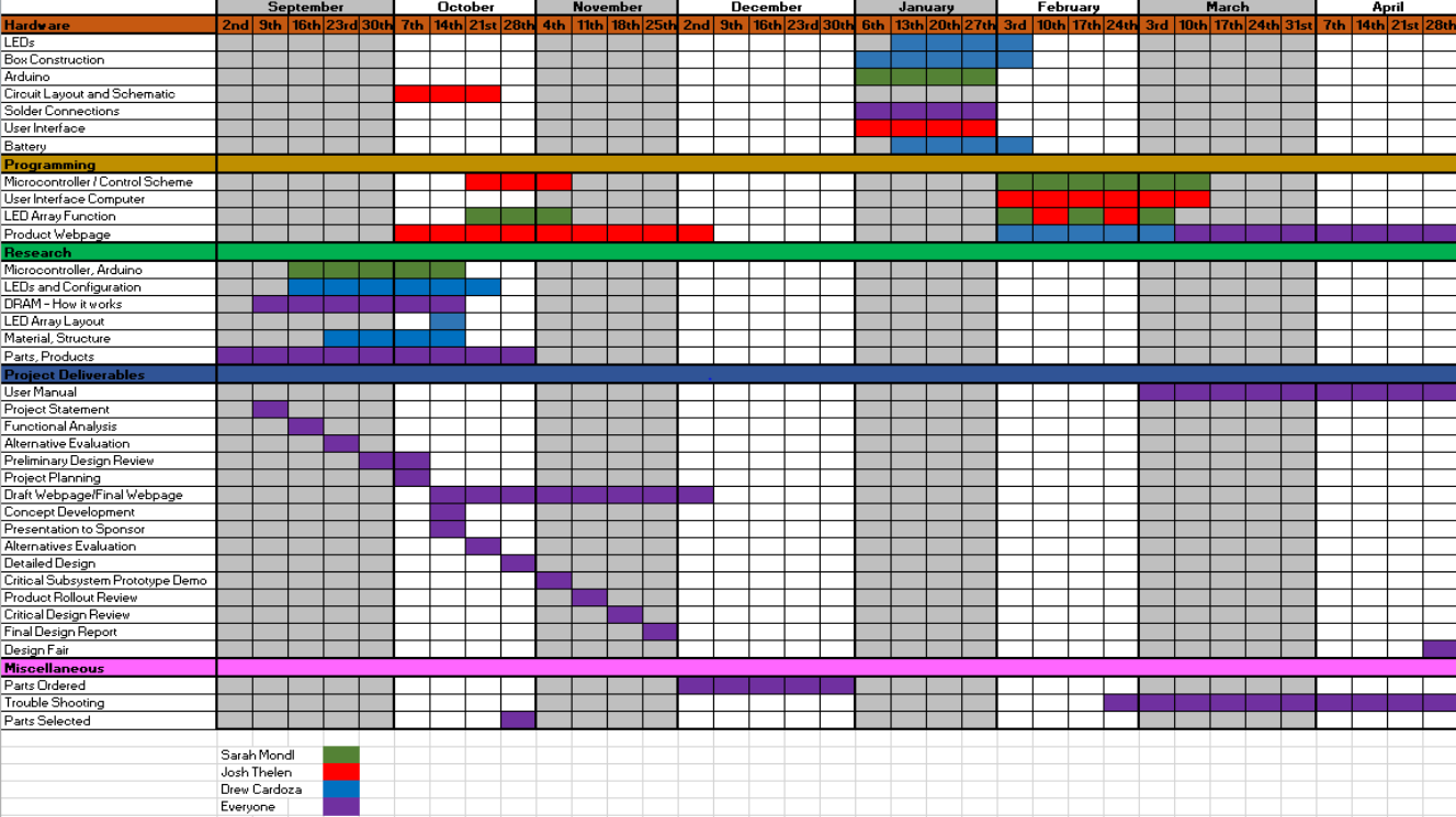
Project Schedule
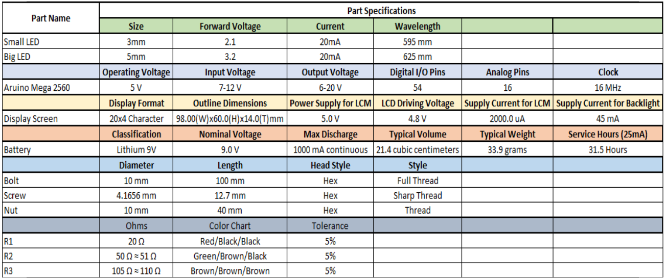
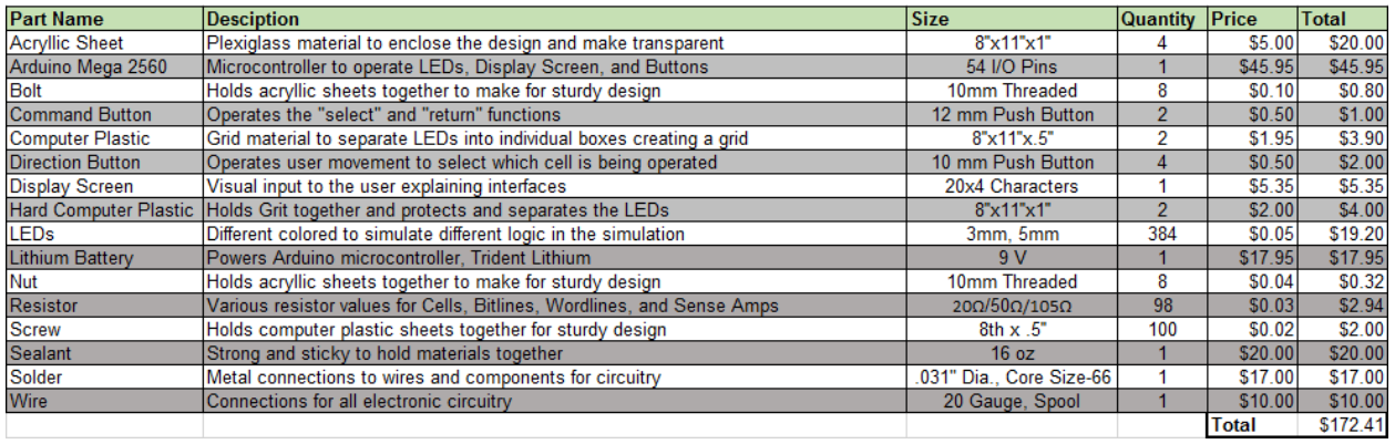
Project Parts List