

 |
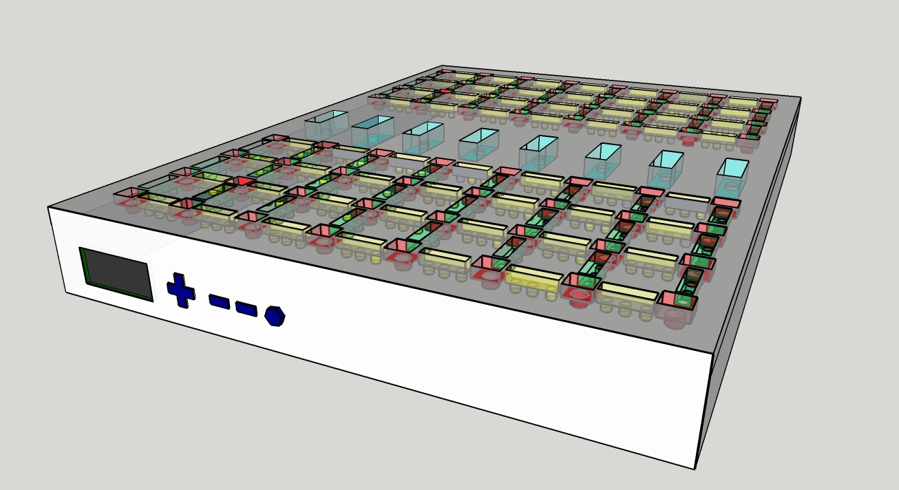
The users interface is operated by means of the LCD and
four buttons on the front panel. Upon booting up the LCD will
display an option on both the top and bottom line. The <
symbol is used to indicate which line is selected and a (v) or (^)
symbol is used to indicate there exists more options that can be
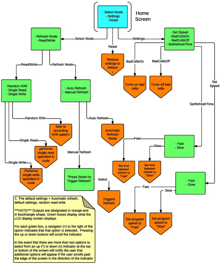
scrolled to bellow the bottom line or above the top line. In order to scroll the < cursor and select new lines, the up and down arrows are used. In order to select a line, the select button is used. Once a line has been selected, the program will navigate to a sub menu or execute a program. Which of these two operations is performed is governed by the flow chart seen to the left. In order to go back up to a previous menu the back button is used. The different operation modes are as follows: - Random R/W: sets the board to perform a sequence of reads and writes on random cells in the DRAM array. Each read/write is separated by a random gap of time. - Single Read: causes the board to go through a single read operaion on a preset cell - Single Write: causes the board to go through a single write operation on a preset cell. The opposite value of the what was previously stored is written. - Auto Refresh: sets the board to perform automatic refreshes every set interval of time - Manual Refresh: dissables the autmatic refresh and gives the user the option to trigger a refresh manually - SetBadCellsOn: diables certain preset cells designated as "bad", and enables spare cells that will be read/write to in place of the bad cells. - SetBadCellsOff: enables the cells disabled by the previous command - SetSpeed Fast/Slow: sets the delay between each step in a read/write routine to either a preset large or small value - SetRefreshTime Fast/Slow: sets the delay between refreshes to either a preset large or small value - Reset: sets the program to Random R/W, Auto Refresh, BadCellsOff, Slow RefreshTime, Slow ProgramSpeed |
| LEDs | Red White Yellow Blue |
| LCD | Product Page |
| Arduino | Product Page |
| Buttons | Product Page |