Key Accomplishments
Semester 1
Class Work
PDR (Preliminary Design Review)
The PDR was presented to all teams' members and advisers, the professor, and several second semester senior design students. Of note, two different sensor types will be tested to determine which method of measurements will be used going forward.
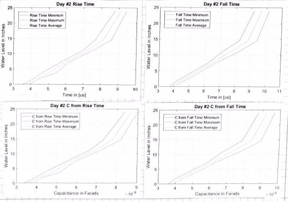
Capacitive Liquid Level Sensor (Sensor Alternative)
Initial tests for the capacitive liquid level sensor showed too much variance during testing to be able to fulfill the key requirement of accuracy. Further tests will be conducted to determine Gaussian distribution of the capacitance measurements to determine a more precise accuracy of the sensor. But for now the Hall Effect Flow Sensors will be the primary sensor moving forward.
Hall Effect Flow Sensor (Primary Sensor)
The first round of tests using the flow sensor showed that one sensor causes minimal foaming of the carbonated liquid as it passed through the system. A second flow sensor was placed in series with the first to determine if a second sensor for the sake of redundancy would be feasible. However, the second flow sensor caused a significant amount of foaming of the liquid. Moving forward, if a single flow sensor does not fulfill accuracy requirements, then a more expensive flow sensor will be sought as opposed to a redundant sensor in series with the first.
CSD (Critical Subsystem Demonstration)
The purpose of the CSD was to show that the flow sensor could give an output as liquid flowed through it and that the output could be interpreted to an amount of liquid. Water was sent out of a water bucket, into a plastic tube, through the flow sensor, and an Arduino Due connected to a computer gave an output that was equated to the liquid flowing through the sensor. Moving forward, the amount of liquid will be correlated to the pulses received by the Arduino Due. Then further tests will be run to identify accuracy while at various rates of the flowing liquid, under pressure, and at kegerator temperatures.
CDR (Critical Design Review)
The purpose of the CSD was to show that the flow sensor could give an output as liquid flowed through it and that the output could be interpreted to an amount of liquid. Water was sent out of a water bucket, into a plastic tube, through the flow sensor, and an Arduino Due connected to a computer which gave an output that was equated to the liquid flowing through the sensor. Moving forward, the amount of liquid will be correlated to the pulses received by the Arduino Due. Then further tests will be run to identify accuracy while at various rates of the flowing liquid, under pressure, and at kegerator temperatures.
Testing, Design, Programming
Capacitor Sensor
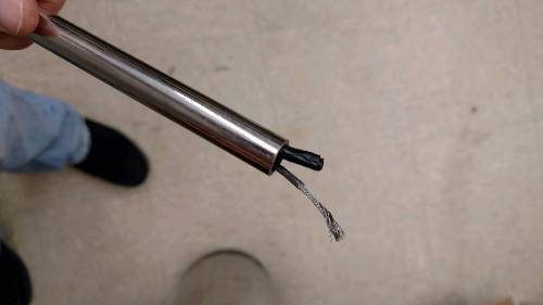
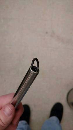
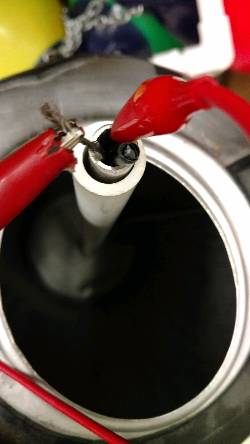
A liquid capacitance sensor was built as a secondary sensor. Class requirements as well as directions from the adviser required that the team not only study feasibility of multiple sensors, but further research into the sensor was needed. Using an insulated wire and a stainless steel tube, a capacitor was built and measurements were taken at water was poured into the tube to act as the dielectric material.
Hall Effect Flow Sensor
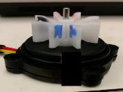
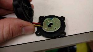
Next a Hall Effect liquid flow sensor was studied. This would be the sensor type ultimately used in the final system. It doesn't require modification to the keg as would be needed for setting a capacitor inside of the keg. The sensor fits in-line with the tubes, so as liquid passes out of the keg, the sensor measures the amount of liquid through the hose and will relay this information to the Arduino to tell the user how much liquid remains in the keg. This works by a transistor and spinning magnet within the sensor. As the poles of the magnet spin past the transistor, the gate of the transistor is opened to allow current to flow. Everytime the gate of the transistor opens, a voltage is seen on the yellow data line of the sensor. This opening and closing of the gate appears as a square wave when connected to the oscilloscope.

Semester 2
Class Work
PRR (Production Readiness Review
Discussed everything accomplished during semester 1 as well as showed detailed timeline and workload distribution planned for semester 2.
Prototype Rollout
Discussed detailed analysis of all testing outcomes. Went over design of printed circuit board (PCB). Showed all programming accomplished to date. Sponsor delivered a new sensor to be used for the rest of the semester. Sponsor also brought up a new request to build a container for the Arduino, PCB, and LCD display; not a level 1 requirement.
Testing, Design, Programming
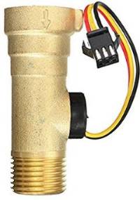
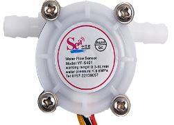
Brass Flow Sensor
To meet food safety standards as well as falling within the small budget, two $10 brass sensors were purchased from Amazon. At first, under directions from the adviser, several weeks of testing was done using tap water. This was 14 kegs of water was run through the sensor. Tap water is not what will ultimately be measured but it was necessary to check consistency of the sensor for several weeks before beginning tests of carbonated water of a thicker density.
After moving onto carbonated water and sugar water and carbonated sugar water, the brass sensor began to move to more and more inconsistent readings. Before this, Becky had brought up the idea that the sensor wasn't reading as accurate because of the low flow rates. Upon hearing this, the adviser directed us to order another brass sensor and to continue testing in the same manner as before.
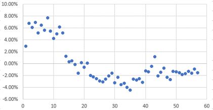
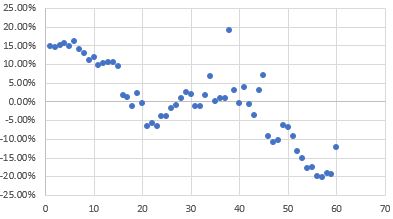
The percent errors over pour numbers are shown in the graphs below.
New Low Flow Sensor
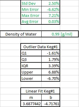
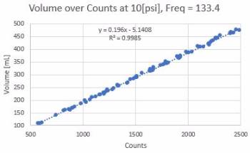
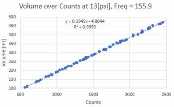
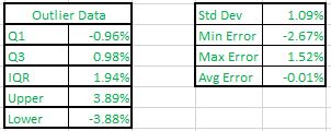
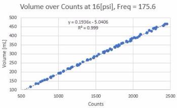
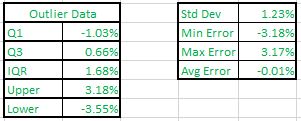
It wasn't until the prototype rollout that the sponsor purchased and provided the team with sensors that would read more accurately at lower flow rates. Upon receiving the new sensor, Chris spent another 18 hours in the lab testing the sensor at different densities of carbonated sugar water and at different pressures, which showed consistant flow rates (frequency).
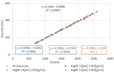
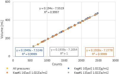
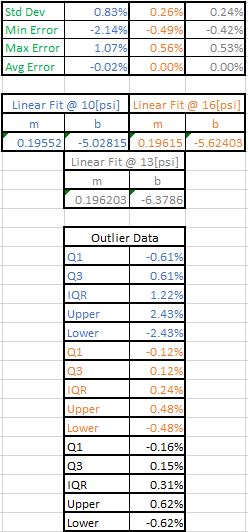
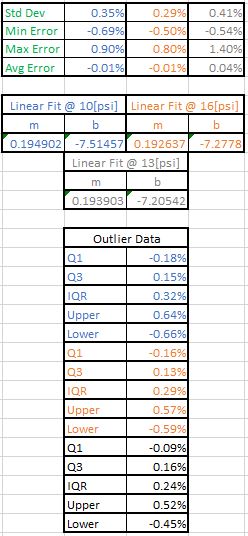
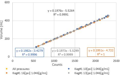
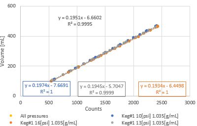
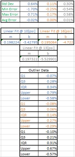
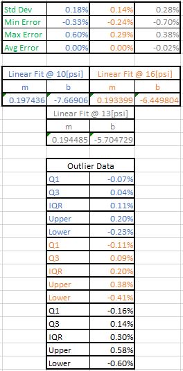
The information was further consolidated and graphed by pressure.
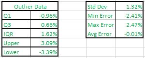
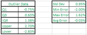
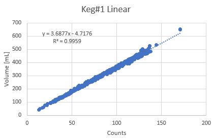
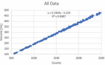
Then every data point from the tests of the new sensor were combined to find the following relationship.
Programming
Programming the microcontroller has been done using the Arduino IDE sofware, which can be used on any Arduino board. The overall goals of the program are to count the pulses from the Hall Effect sensor, to display the liquid remaining in the keg (in half pints) to an external LCD screen, to allow the user to input the initial size of the keg (in gallons) and to store the sensor lifetime data to nonvolative memory. Additional coding goals include allowing for the addition of sensors. The pulses from the Hall Effect Sensor are counted by using the interrupt command on the Arduino. The interrupt counts the rising edge of the square pulse that is being sent by the sensor. After testing, a calibration has been determined which is used to adjust the amount of counts per pint in the code and this value is displayed in amount remaining in the keg on the LCD screen using the Adafruit_RGBLCDShield.h library. The LCD screen contains a menu where the user is able to input the starting volume (in gallons) of a new keg. This menu is a drop down list of common keg sizes. Using the EEPROM.h library, the sensor lifetime data is stored to EEPROM where the memory is saved even in a power off situation.
PCB Design
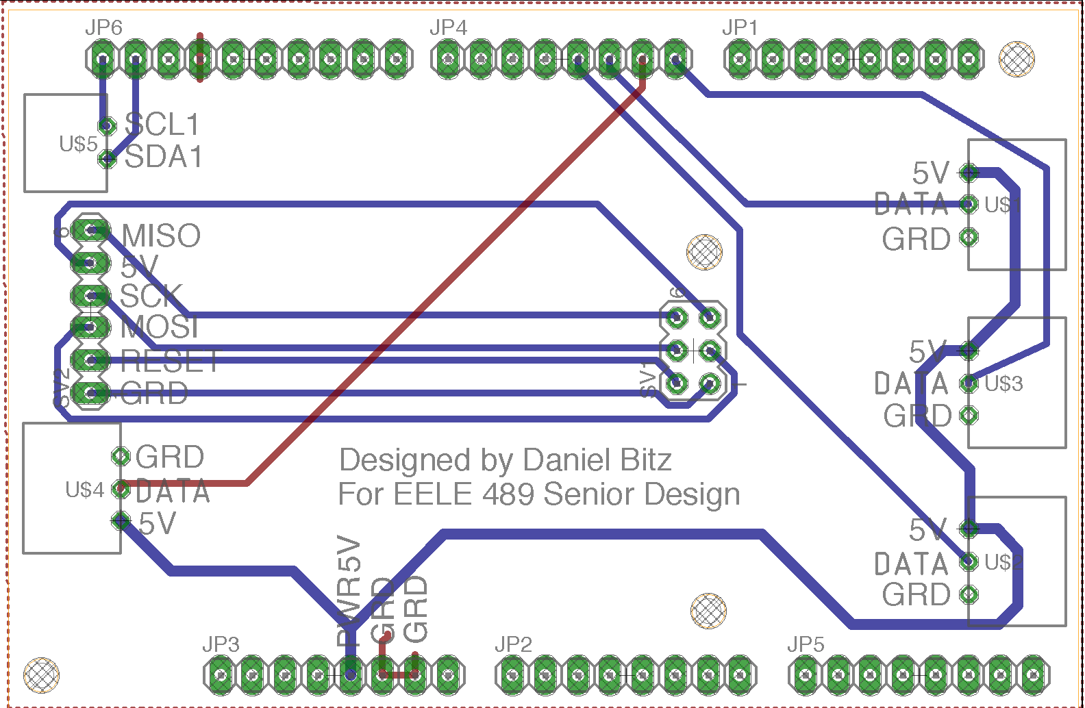
The PCB was designed using the EagleCAD software and involved many hours of learning the functionality of the software. The PCB was designed to sit on top of the Arduino microcontroller. The pins attached to the PCB line up with the pins on the microcontroller, allowing the use of right angle connectors on the PCB. This allows for the user to be able to plug the sensor directly into a port on the side of the PCB instead of having to deal with finding the right pin on the Arduino board itself. The LCD screen's pins line up with the top of the PCB and there is no loss of functionality. The layout of the PCB allows access to all the necessary pins on the Arduino through the ports on the side of the PCB. The schematic and board layout are shown below.
PCB Schematic

PCB Board Final Layout