System Overview

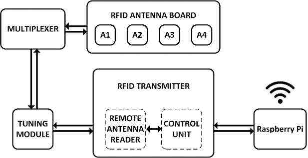
Subsystem Block Diagram showing how each sub-system is interconnected with the others within the Main RFM Unit.
Each subsystem plays a vital role in the functionality of the Main RF Unit. There are five separate sub-systems in the unit itself - The Multiplexer, Surge Arrester, RF Module, Raspberry Pi (Graphical User Interface) and the Power Board. If one of these sub-systems fails then the entire system will fail to function properly.
Sub-system Breakdown
The first board to receive any input will be the Power Board. The Power Board will receive either an AC or DC signal from some external source; oftentimes this is a solar panel as this provides the power needed for the unit to function while also having minimal dependencies out in the field. Each of the other sub-systems is connected to the power board and will receive the proper input voltage to power the sub-system. This value varies from 5V to power the Raspberry Pi, up to 12V powering the RF Module. The Control Board for the RF module is connected to the Surge Arrester, providing safety from bursts of energy due to lightning strikes in the area of the unit that the antennae might receive. The Raspberry Pi acts as the brain of the unit, collecting and storing the data the antennae receive when a fish passes over it. This happens over a USB-to-RS232 connection to the Control Board of the RF Module. Once a user is ready to collect data from the unit, either a wireless connection is established with a laptop or is connected through an Ethernet connection, and the user can then download a Comma-Seperated-Value (.csv) file that is ready to be analyzed through an application such as Microsoft Excel, or MATLAB. The software written for the Raspberry Pi will repeatedly send a "send" and "receive" command to the RF Module, which is how the antenna decides what to do when a fish is overhead, thus completing the functionality of the system.
