
Key Accomplishments
Power Supply
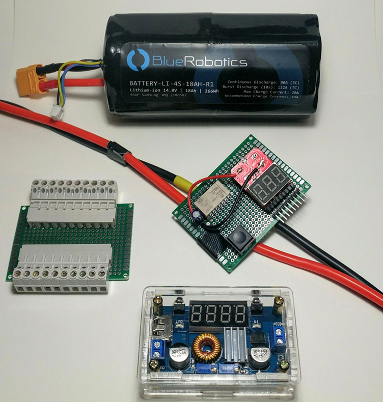
Testing the battery protection circuit.
The previous sub had a complicated power system that required simplification to ensure efficient distribution of power and allow future teams to make modifications easily. Custom batteries with limited availability were used, prohibiting the team from picking up additional units were they to experience failures. Additionally, the addition of a faulty power supply caused a current draw from the old batteries, eventually draining the batteries of charge to a point beyond compare.
The power distribution subsystem begins with two 14.8V 18Ah 4 cell lithium ion batteries connected in parallel to give 14.8V with a combined capacity of 36Ah. The batteries are connected thru the balance plug to a protection circuit designed to disconnect the battery if any one cell drops below a set voltage.
The main battery cables are connected to power lugs inside the capsule. The power lugs will provide 14.8V to the motherboard, GPU, ESCs and various other components including a DC to DC buck converter that will step down the 14.8V to 12V DC. The 12V will be supplied to the pneumatics control board used to operate the arm.
By simplifying the design as such, it will be easier to diagnose and troubleshoot problems. Additionally, the efficiency of the system will give the sub a larger run time and provide adequate warning time to the team when it is nearly time to recharge.Processing Unit
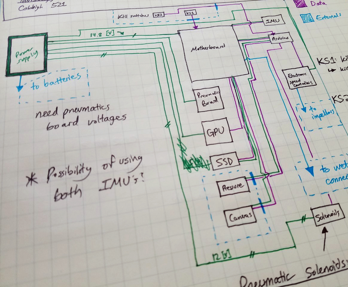
Preliminary wiring sketch for the processing system.
As the sub carries through the course, it will need to assess its surroundings and autonomously make decisions based on what it senses. This is the core purpose of the processing unit - a network of devices under the command of a single master controller that determines the sub's status and responds appropriately.
Said master controller is an Arduino Mega 2560, the same microcontroller used on the previous sub. It continually receives updates from the rest of the sub and distributes commands in response to the inputs. The sensors include an inertial measurement unit (IMU), the pressure sensor, the cameras, and two kill switches to cut power from critical components in the case of an emergency.
Of the utmost importance to the sub's operation are the cameras and graphics processing unit (GPU). The previous year's sub used a NVIDIA GeForce GTX 980 to handle the video input from the cameras and forward it to the motherboard; however, the device has proven to be too large, too heavy, and produces considerable heat. Our solution is to replace this GPU with the NVIDIA Jetson TX2 board, a small, lightweight, and exceedingly powerful device that matches the performance of the GTX 980 while reducing its effects on the sub's weight and buoyancy.
Interpreting the data from the GPU is the motherboard. The previous sub used an ASRock B85-ITX with a fourth-generation processor; however, the configuration has since proven to be too large and too heavy. Additionally, the motherboard itself has limited availability and hinders future teams from further development of the system. Thus, our team has selected the Intel NUC to replace the previous motherboard. The kit includes 16 GB of Optane Memory, a seventh-generation, quad-core i7 processor, and a small, compact size and weight.
All other sensors, save the Arduino, will be upgraded to the current generation model in order to standardize this year's sub and provide a solid groundwork for future teams.
Electronics Rack
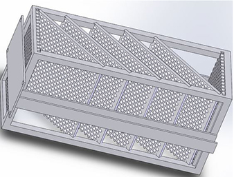
Rendering of the electronics rack design.
The electronics rack is designed to allow for the electronic sub-assemblies to be rigidly mounted to the submarine. For the sake of electronics performance and submarine mobility, nothing inside the bulkhead capsule can be permitted to slide, move, or even vibrate.
The rack is mounted to the capsule bulkhead using four ¼ 20 UNC bolts. The electronics will be mounted to individual plates and slid into channels in the frame. Two channels are run down the sides of the frame to allow for wiring runs to the individual boards. The individual boards made of ¼ inch thick perforated aluminum. The perforated holes allow for boards of any size and shape to be mounted securely. The entire frame and boards were designed out of aluminum to allow for maximum heat transfer out to bulkhead and surrounding environment.
Additionally, the rack leaves room for additional components and can be easily removed from the rest of the sub for maintenance and monitoring.
Bulkhead
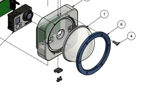
The stiffening ring to be added to the camera housing.
The previous bulkhead allowed water to leak into it due to poor sealing and design, thus risking damage to the electronics within. The two camera housings that are directly connected to the outside of the bulkhead are made of plastic; when the bolts used to secure the housing to the bulkhead were tightened, this caused the camera housing to warp. This warping allowed water to infiltrate into the bulkhead.
Our solution to this problem is to add stiffening rings made of aluminum to each camera
housing. This will allow the bolt pressure to be applied more evenly and prevent the
plastic camera housing from warping. With this fix, we hope to eliminate leaks from
the bulkhead design and protect the electrical components from damage.