After the difficulties
encountered
in using Euler angles and rotation matrices, the team decided to use
quaternions and vector math to calculate and visualize the
rigid body orientation of the IMU. Quaternions are a nice
mathematical concept to use for orientation and attitude visualization
for navigation designs. Quaternions are an extension of imaginary
number set, commonely refered to as a hyper-complex number. A
quaternion can be thought of as a four element vector. This
vector is composed of two distinct components: a
scalar and a 3 element unit vector. The scalar value, w,
corresponds to an angle of rotation. The vector term, [x y
z],
corresponds to an axis of rotation, about which the angle or
rotation is performed.
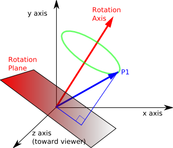 Figure:
Quaternion
Figure:
Quaternion
Constructing a Quaternion
n = |V x V'| = |V||V'|sin(θ)
θ = arcsin(n/(|V||V'|))
q = [q1 q2 q3 q4]
q1 = cos(θ/2)
q2 = sin(θ/2)*nx
q3 = sin(θ/2)*ny
q4 = sin(θ/2)*nz
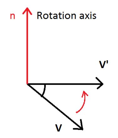 Figure:
Calculating a Quaternion Via the Cross Product
Figure:
Calculating a Quaternion Via the Cross Product
The
image and equations above demonstrate how a quaternion representing
rotation can be calculated by way of the cross product identity.
Taking the cross product ofan initial vector V and the
rotated
vector V' the axis of rotation n is obtained. By manipulation
of
the cross product rule, the angle of rotation θ can be calculated.
The final four equations shown above demonstrate how the four
quaternion terms are calculated using the angle of rotation and axis of
rotation information. For our design, quaternions for
rotation
will be calculated by tracking the changing gravitational and magnetic
field vectors (in the body frame) as the IMU moves and rotates.
Rotations Using Quaternions
Once
a quaternion representing orientation has been calculated, the computer
rendered model of the IMU is rotated to match this orientation by
applying the quaternion to each of the vertices describing the sensor.
This is carried out by way of the following equation:
v’ = q⊗v⊗q’ where q’ =
[q1 –q2 –q3 –q4]
In the above equation, the
operator ⊗
represents quaternion multiplication. The equations below
shows
mathematically how quaternion multiplication is carried out.
It
needs to be noted that before carrying out this operation, the vector
describing the vertice that is to be updated must first be converted
into a quaternion. This is achieved by simply using the x,y,
and
z components of the vertice as the q2, q3, and q4 terms and inserting a
placeholder q1 value of 0, representing no rotation: q = [0
Vx
Vy Vz].
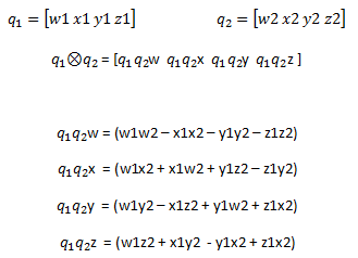 Figure:
Quaternion Multiplication
Figure:
Quaternion Multiplication
Orientation Visualization with Quaternions
The video below shows
a MATLAB script output that visualizes our rendered sensor rotating via
quaternions. In this example, synthetic magnetometer data was
created that corresponded to a series of rotations about the body X, Y,
and Z axes. This synthetic data was then ran through a script
that calculated the overall system quaternion that
corresponded
to each measurement. These quaternion values were then used
to
update the location of of the body vertices, resulting in orientation
visualization.